

安装 Steam
登录
|
语言
繁體中文(繁体中文)
日本語(日语)
한국어(韩语)
ไทย(泰语)
български(保加利亚语)
Čeština(捷克语)
Dansk(丹麦语)
Deutsch(德语)
English(英语)
Español-España(西班牙语 - 西班牙)
Español - Latinoamérica(西班牙语 - 拉丁美洲)
Ελληνικά(希腊语)
Français(法语)
Italiano(意大利语)
Bahasa Indonesia(印度尼西亚语)
Magyar(匈牙利语)
Nederlands(荷兰语)
Norsk(挪威语)
Polski(波兰语)
Português(葡萄牙语 - 葡萄牙)
Português-Brasil(葡萄牙语 - 巴西)
Română(罗马尼亚语)
Русский(俄语)
Suomi(芬兰语)
Svenska(瑞典语)
Türkçe(土耳其语)
Tiếng Việt(越南语)
Українська(乌克兰语)
报告翻译问题


In the newer builds (which I haven't really played because I don't like the newer game features personally) I've seen people on Discord talking about the car not starting or running properly due to the CAS (Cam Angle Sensor) being out of position, and that's what I assume is the little gizmo that reads the cam position and relates that to engine RPM and then calculates and cam advance needed.
Whether anything will change in the future, we'll just have to wait and see.
They're talking about things that could potentially hint at things like that becoming possible, the addition of a strobe light for checking the timing for instance, so you never know what's in store.
I wonder, has anyone experimented with advancing/retarding timing yet? ik the game is still early access but I joined this party kinda late lol
The timing being out is probably the most common thing people get wrong, and is usually always the reason for backfiring and low power.
Just for reference - a stock motor in A1 condition should be putting out about 140hp (up to around 145hp if you use 4-2-1 headers and an ITB kit in place of the stock items, and those can still be used in Limited Class races at the current time legally), or 240hp with a turbo kit installed.
If you get to Level 30 and unlock the Golden Dipstick, then that Dipstick will add a permanent 10hp to every car you fit one to, and can be used in both Limited and Unlimited class races legally.
Pro tip there the devs don't, and won't tell you about. 😜
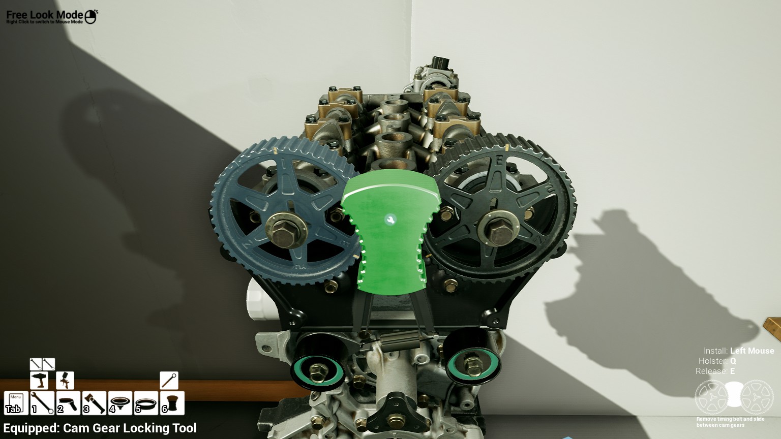
I was able to install the cams, thank you!
I think I may have the solution to your issue.
The "M10 x 35mm" bolts didn't work for me either. I noticed that the picture EssBee provided for the cam gears have bolts with a thick base under the bolt head (like a washer).
The ones I got to work were the "M10 1.25 x 35mm" and look the exact same in the picture.
Hopefully this helps!
Once I get to the cam gear stage, I will let you know if I come across a work around. Thank you so much for the tip!